MY FIRST REAL HAM RADIO ANTENNA ON MY STONE ROAD HOME:
ERECTING THE DX-77 HF ANTENNA

June 8 & 9, 2001

DX-77

Hy-Gain DX-77


INTRODUCTION

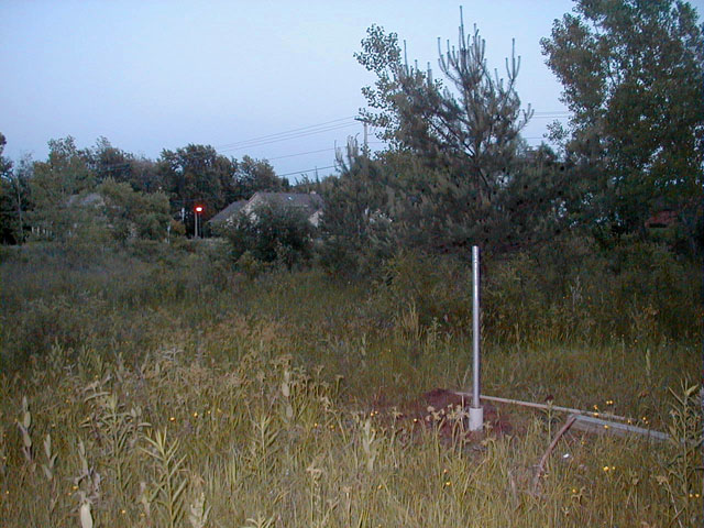
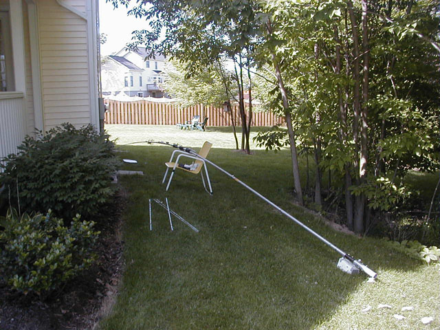
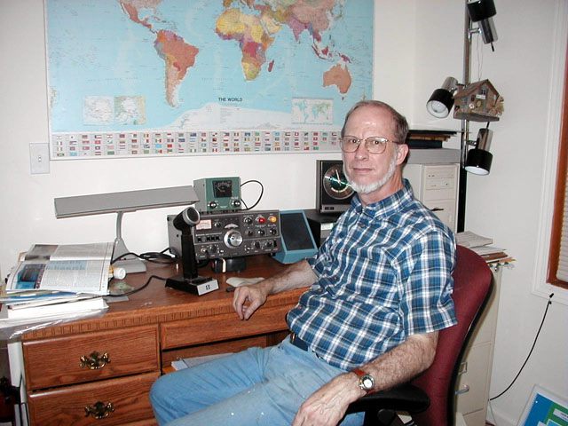
Below is a series of shots showing the erection of the first real HF antenna at the new house.

The location is in the vacant land to the East of the house, about 75 feet away. The location is about 150 feet from the road and is somewhat hidden by the young trees between it and the road.

The pipe I chose to use is the bottom section of a 40-foot telescoping mast that my good friend Jim Fitzreiter, K3QHO, gave me 25 years ago. I used it to support my first antenna at my new home when we moved to Rochester in 1976. That mast supported a trap dipole (inverted-V) for several years before being replaced by a 30 foot tower and a Mosley TA-33 tribander.

The bottom section next saw service as the pedestal to support our bird feeder and was in place about 15 years. Today, it will be the base for another antenna I bought used at the Rochester Hamfest in June 2001.
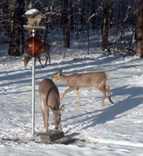
Deer(The photo at the right is the deer at the old house admiring the pole holding the bird feeder.)

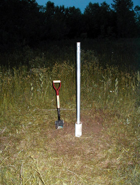
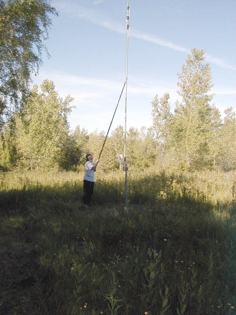
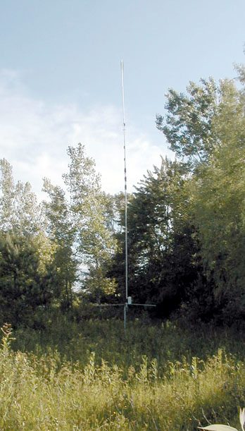
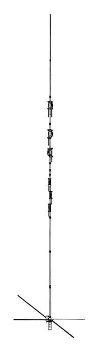
The antenna is a 30-foot end-fed self-supporting vertical shown on the left. Believe me, it is a real tail wagging a dog.

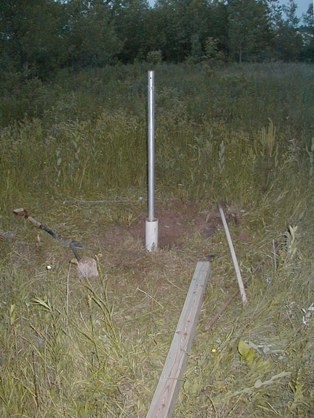
The Hy-Gain installation instructions call for a two-inch pipe three feet in the ground surrounded by concrete. Not wanting to lock this old and trusty pipe into a marriage with a hundred pounds of concrete, I tried to come up with an alternative. I could not pound the pipe into the ground more than a foot, in spite of what appeared to be fairly soft ground. However, this did not surprise me as the land around the house is peppered with stones of all sizes and I thought this may be just the same.

My next and really the first step, was to try to dig a hole in the ground to see what the soil was like. Much to my surprise, I was able to dig a three foot hole and never even seen a rock, not one! Not even one the size of a pea! I could not believe it. The soil is nothing but sand below four inches of topsoil.

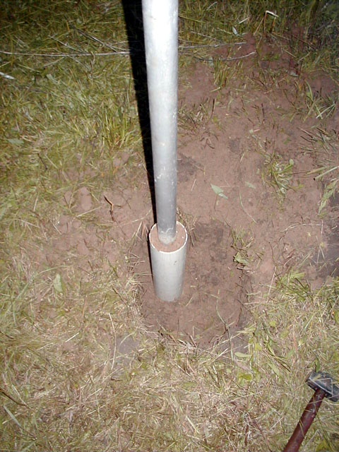
Trying to avoid concrete, I remembered what one old timer told me, "It is not the weight of the concrete that is used to keep the tower or pole erect, it is the surface area." So, I decided to increase the surface area of the two-inch pipe by placing it into a scrap of four-inch pipe. The I hammered the two-inch pipe as far into the soil as I could--about eight inches-and filled in the larger pipe with the sandy soil. Voila! The pipe now has an effective diameter of four-inches. It will take twice as much pressure to displace the earth outside the pipes and I will be able to easily dig up the pipe and move it to another location, if it is required.

To keep the antenna from swaying too much in the wind, I am planning on guying it with some black Dacron rope.

Keep tuned for updates on this page.

73,

Chuck
K3NAU


PHOTO GALLERY OF INSTALLATION

(Click on any photo to enlarge it.)


STEP 1: Digging the hole and installing the mast.

Loading...

A Pole in Outstanding in his Field

Overview of the installation site. Looking South.  

Loading...

The Tools at the Site

Overview of the work site. The 4-inch beam was used to tamp the soil as the hole was filled in. A small piece of molding was used to tamp the soil (sand) between the inner and outer pipes.
         

Loading...

I decide to throw in the shovel.

The finished installation as the sun set behind me. About four-foot of pipe extends above the surface.  

Loading...

Looking into the Sandy Pit

Close-up of the hole and pipes. I should have centered it; this would have made tamping the soil easier, but no one is perfect. I used the piece of molding to tamp the soil and finally my foot.


STEP 2: Mounting the antenna to the mast.

The weather was picture-perfect. Clear skies, temperature around 75 and just a hint of a breeze. I got my son Tom to help out with the antenna erection. There was no way that I could imagine doing it myself.


The Temporary Workshop
I set up my field workshop on the East side of the house. It was shady and the temperature was about 75 degrees. Each coupling needed to be sanded, cleaned and the covered with an anti-oxidizing paste. The re-assembly and measure. In all, two hours work.

Tom Lends a Hand

Tom helped me erect the antenna. The first attempt was a failure. He could not control the antenna while I inserted the bolts in the base clamp. The antenna weighs 30 pounds and is 29 foot long. That is real tough to control from the base.

I decided to temporarily "guy" the antenna to steady it after we got it in a vertical position. I crafted a support pole from an old 10 foot telescopic pole from a swimming pool skimmer. I wrapped 10 inches of a webbed Nylon band around the antenna, then clamped the loose ends to the end of the pole with a hose clamp. We then twisted the pole and band until it was tight and it was read for use.

After the antenna was swung into a vertical position on a temporary hinge, Tom used the pole to steady the antenna as I worked on the base. This arrangement gave him considerable control over the antenna, but it was still a bit of a struggle.

When the base plate was secure, the control pole was twisted to loosen the band, and was then slipped down the antenna and detached.


The Hy-Gain DX-77 proudly standing in the Dell.
This is the final installation with the exception of the repair of the five-foot radials at the bottom. The clamps were damages and spares are on the way. Now it is off to hook up the coax.  

DX-77 Dimensions

Post Installation Thoughts

Installing the DX-77, I learned some things that should have been in the manual. Read about these below.

A PDF version of the installation guide is available free-of-charge on the Hy-Gain Web site.

A reference drawing of the antenna's dimensions on the left.


STEP 3: Test it out. Will it work? If it does, how well?

After the antenna was in place and I had dinner on the back porch, I decided to tackle testing the antenna.

I found a long length of RG-58 that I had for nearly 20 years in the garage.This will not be the permanent feedline, but it was good enough to make a field test. I put one connector on and connected it to the antenna, then I fished the cable through the cellar wall next to the power line. Not very safe for the long run, but OK for now.

After the PL-259 connector was in place on the basement-end, through a series of adapters, I hooked it up to the unused cable TV run to my office on the second floor. (OK. So the impedance of the TV line is 72 Ohms, the mismatch will not hurt much and it just might help.) I dug out the old Kenwood transceiver and carried it up to the office to the ham radio desk. With the help of a couple of adapters, I connected the radio to the antenna system. Of course, it did not work the first time as no one had bothered to label all of the TV cable runs throughout the house. After four tries, I got the right one and the signals were loud and pretty clear. Guess what? The SWR is just great on all of the bands!


The Old Man Himself
K3NAU

Here I am shortly after my first two contacts with the new antenna and from the new QTH! I am tired, dirty, smelly and HAPPY!

(I did not smile as my teeth needed brushing. And, I know I should have sat up straight in the chair.)

I got good reports from a 40 meter station in Virginia, and from a fellow operating on 20 meters in Atlanta, Georgia. I hear many stations from all over north and South America and a fellow from Czechoslovakia. One of the guys said the bands were in band condition. With that evaluation, I am doing just great!

The real "shack" is hanging on the lamp post behind me.

I will promise to clean up the area for the next photo. ;-)


"The Shack"--The first setup of the ham radio station

Here is the initial ham radio setup. This is to the right of my computer desk. On the left is my trusty HF radio transceiver--the Kenwood TS-520S. Still working after over twenty years of service. The power output is still about 100 Watts on 40M.

It is too bad that it does not work on the two "new" ham bands, but right now, I do not care a lot about that; my station is back on the air!

To the right of the is a little older antique, the Drake SPR-4 shortwave receiver. It is hooked up to a 50-foot longwire that runs from my window sill to a small tree in the back yard. It is surprising how well such a simple antenna works when connected to a good receiver.


I AM BACK ON THE AIR!

I AM BACK ON THE AIR!

I AM BACK ON THE AIR!

My next projects are to put up an 80M dipole, properly install the feedline to the antenna, and put ups some guy lines on the DX-77 vertical. The feedlines will go through a 1-1/2 inch pipe from the basement to the field. Finally, I will put in a ground rod and lightning gap at the vertical's base. Just for safety sake.

Now, I have to make a commitment to use this nice installation on a regular basis. Ah... another challenge!

73 from Pittsford, New York,

Chuck
K3NAU

P.S. On April 4, 2003, the antenna came thundering down in the second day of an ice storm. Visit my photo album page to see details.

POST INSTALLATIONS OBSERVATIONS & RECOMMENDATIONS

I had a couple of problems that may be worth noting and correcting in your installation.

  1. The assembled antenna is a bit top heavy and like holding a fishing pole with one hand while a 6 pound trout is on the end of the line. I strongly suggest assembling the lifting aide I show on the Web page. It will be virtually uncontrollable unless you can stand with your feet apart and at the same level as the hinge point. Oh yes, do not attempt to put it up in anything but a calm day.
  2. Consider guying the antenna. It is rate at 60 MPH. Sure thing! It swayed considerably after I first installed it on a day with many 20 or 30 MPH winds. Do not leave anything to chance. It is a nice antenna and an expensive source of scrap tubing. I bought some cheap black poly rope and guyed it about two-thirds from the top. I sleep well at night.
  3. Buy some spare parts. The V-shaped brackets that hold the radials to the mast and the large bolts that forms the hinge and mounting brackets. I twisted one into a snake shape after the antenna fell over on the first attempt to put it up. There is a lot of torque on those bolts.
  4. Do not mount the radials at the time of erection They are a safety problem and are likely to get bent or broken.
  5. Install the big pass-through bolt on the mounting clamp to use as a hinge to raise the antenna.
  6. Put some electricians lubrication on the telescopic joints. It has some graphite in it to provide some conductivity. The joints include only those of the main telescopic sections and the radials. (Actually, the radials are part of the transmitting element and not a counterpoise as in ground plane antennas.)
  7. Make sure all hose clamps are fully stainless steel and TIGHT! I had the top section drip down about a foot and the whole antenna system went to Hell.
  8. Remember--SAFETY FIRST! This is a two-person job at a minimum, three would be better. Do not attempt to do it on your own; you will destroy the antenna or kill yourself, particularly if you are installing it on a rooftop. Leave the beer in the fridge until the installation is completed!
  9. If you are installing the antenna at ground level, I would suggest protecting your eyes from being poked by the radial arms. I bought some inexpensive 1-1/2 inch foam fishing bobbers and removed the hooking mechanism. Then I enlarged the hole to be slightly small than the end of the radials and glued them in place with a little RTV. You can still trip over the antenna, but you will not puncture any part of your body! As my doctor told me, "Do not put any more holes in your body than what God gave you."
  10. Measure the sections carefully. There is a really good chance you will not need to adjust the antenna further. The antenna is really an off-center feed dipole. The height above ground (conductive materials) will be of some influence but not a lot. This should mean a fairly stable SWR as ground water conditions change with the seasons. It will not eliminate the influence of water, snow or ice on the structure.