| 2,240,449 200 kc VARIABLE-FREQUENCY CRYSTAL Patented April 29, 1941 |
| 2,240,449 200 kc VARIABLE-FREQUENCY CRYSTAL Patented April 29, 1941 |
This is a third patent for a variable-frequency crystal invented by John M. Wolfskill, W3QKT. The patent claims the unit has a frequency spread of approximately 200 kc at a fundamental frequency of 3,500 kcs. With the unit in a circuit producing a frequency doubling, the spread would be twice that or nearly the whole 7,000 kc ham band.
This crystal unit was never commercialized or sold. It is part of a suite of patents for variable frequency products including an oscillator and a frequency mixer (synthesizer) for the amateur radio market. The advent of World War II silenced the radio amateurs for the duration of the war and the market after the war was flooded by millions of cheap crystal units suitable for amateur radio use.
TECHNICAL ILLUSTRATIONS
|
 |
This invention relates to a variable frequency piezoelectric apparatus generally. More particularly this invention relates to piezoelectric crystal oscillator apparatus in which the frequency may be readily adjusted throughout a wide range.
An object of this invention is to provide a quartz crystal controlled apparatus, the frequency of which may be varied over a wide frequency range; by a wide frequency range is meant a frequency of up to several hundred kilocycles.
Another object of the invention is to provide a crystal oscillator employing a holder of special construction that can be used in conjunction with a special type crystal, so as to facilitate rapid variation of the crystal frequency.
Another object is to provide a wide range adjustable frequency quartz crystal having a low frequency temperature coefficient over the complete variable range.
Still another object of this invention is to provide an adjustable frequency piezoelectric crystal apparatus particularly suited for high frequency operation.
A further object of this invention is to provide a piezoelectric crystal controlled oscillation generator in which the frequency may be varied up to several hundred kilocycles.
The use of a variable frequency oscillator has become more and more important in the communication art, particularly in the amateur field. As a result, various methods have been devised for varying the controlling frequency. Electron coupled oscillators of various types as well as variable frequency quartz crystal controlled oscillators are being used. The variation obtainable with a single quartz crystal by present methods known to the art is relatively small, and is considered insufficient for various services. The advantages of a quartz crystal controlled oscillator over the self-excited type of oscillator are well known to the art, and will not be discussed here.
A method of varying the frequency of a quartz crystal over a relatively narrow frequency range is described in my Patent No. 2,079,540. The invention disclosed in this patent relates to a wedge type adjustable air-gap which is associated with one or more quartz crystals, and the variation of the air-gap controls the frequency variation of the crystals. The frequency variation obtainable by this method, however Is limited to a relatively small percentage of each crystal frequency approximately .17% for a low temperature coefficient type of cut, and this may be increased slightly with other types of crystals. There was therefore a need in the art for a method of obtaining a much wider frequency variation without sacrificing any of the advantages of crystal control. By taking a quartz crystal of more or less oblong shape and grinding it in the shape of a wedge along the longest dimension so that the thickness at one end is such as to give the highest frequency required in the variation, and the thickness at the other end of the wedge is such as to give the lowest frequency desired, a variable frequency crystal is produced. Then by employing a narrow movable electrode and moving it along the length of the crystal, various thicknesses in the crystal will be encountered and different frequency oscillations corresponding to these various thicknesses will be produced. This electrode should preferably be in the shape of a small movable roller which travels along the length of the crystal.
By employing a high feedback oscillator circuit, the crystal can be made to oscillate at any one frequency dictated by the thickness of the crystal at any one particular point or elemental length along its length. By moving the narrow electrode or roller along the wedge crystal continuously varying thicknesses are encountered and the frequency of oscillation varies smoothly and continuously from one end of -the wedge to the other. For a low temperature cut crystal, sometimes referred to in the art as an AT cut, at 3500 kilocycles a difference in thickness at the ends of the wedge of one thousandth of an inch will give a frequency variation of approximately 200 kilocycles; that is, the crystal at one end will be approximately .0177" thick and at the other end .0187" thick. Greater or smaller frequency variations may be obtained by varying the wedge on the crystal. Of course great precision is required in manufacturing the crystal to produce a smooth wedge from one end to the other, that is, one which increased linearly with the crystal length, otherwise frequency jumps are likely to be encountered.
The crystal must also be exceptionally parallel along its width dimension because at any one setting of the roller or movable electrode this small element controls the frequency, and because of its size good activity is required to maintain oscillation.
Crystals of various cuts may be used for this invention, but it has been found that with low temperature coefficient cuts such as the AT cut crystal and also the AC cut (low coupling coefficient to other modes) the variation is smoother and did not require quite as great precision in manufacture to obtain the desired smooth continuous frequency variation. The length and width dimensions of the crystal may be any reasonable values, however good dimensions for practical use are approximately one and onehalf inches long by three-fourths inch wide.
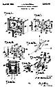
Various features of this invention will be more apparent from the following specification and the drawing in which, briefly, Fig. 1 shows a view of a crystal holder for use with a wedge shaped crystal element; Fig. 2 is a view of a wedge shaped crystal cut; Fig. 3 is a cross-sectional view of the holder taken in side elevation; Fig. 4 is a detail view of a form of contact for the cylindrical electrode; Fig. 5 is a fragmentary view of one end of the cylindrical electrode and tension spring associated therewith; Fig. 6 is a partial view of a holder having two cylindrical electrodes; and Figs. 7 and 8 are circuit arrangements employing wide frequency variation crystal frequency control apparatus.
Referring to Figs. 1 and 3 of the drawing in detail, reference numeral 10 designates the housing in which is positioned a wedge shaped crystal 11, a cylindrical electrode 12 and a base electrode 13. The bottom electrode 13, in this case is flat and the movable electrode 12 is in the form of a roller or cylinder actuated or moved over the top surface along the length of the crystal I I by means of rotatable arms 18, springs 21 such as shown in Figs. 5 and 6 being used to keep the roller 12 in contact with the crystal. The roller 12 should be at least one-half inch or greater in diameter so as to provide a reasonable area in contact with the crystal, otherwise difficulty might be encountered in providing enough feedback in the oscillator to start oscillations.
The roller 12 is provided with pins 16 at its ends for engaging the arms 18 in slots 17 as shown in Figs. 1, 3 and 5. An elongated contact bar 22 shown in Fig. 4 may be mounted in the side wall 10a of the housing to contact a small button or cap 16b pressed against said bar by the spring 16a positioned inside of the cap 16b. The bar 22 is of conducting material as are also the cap 16b, spring 16a and pin 16 so that an electrical circuit is established between the base pin 15 and the roller electrode 12 through these elements. The bar 22 extends over practically the entire length of the side wall 10a so that the contact is maintained with the roller electrode as said electrode is moved over the crystal surface.
It is of course obvious that other ways of connecting the electrode 12 to the pin 15 may be employed, such as, for example a flexible wire 23 made up of a multiplicity of fine wires bunched together may be attached to one of the pins 16 and passed down through a suitable hole in the side 10a and the base to the pin 15. This would be satisfactory in cases where the roller electrode 12 is of sufficient diameter so that it does not complete more than two revolutions in rolling over the crystal from one end to the other.
In Fig. 6 is shown a modified form of holder in which two roller electrodes 12 and 12a are employed and in this case the roller 12a is used in place of the base electrode 13 shown in Figs. 1, 3 and 5. Both of the rollers 12 and 12a may be moved over corresponding surfaces of the crystal by the member 18 in this form of holder and in order to accomplish this the crystal element 11 is supported at its ends by the insulation members 24 and 25. The electrodes 12 and 12a are connected to contact pins 14 and 15 illustrated in Fig. 3 and for this purpose two contact bars 22, one for each roller electrode may be provided or each electrode may be connected through a suitable piece of flexible wire, ribbon or the like. The electrodes 12 and 12a are urged into contact with the corresponding crystal surface by means of springs 21 and 21a, respectively, carried by the electrode support 18.
Various values for the angle q between the optic, axis Z and the principal faces 11a and 11b have been employed in the tapered crystal element. The desirable angles are those between minus 10 and minus 30 degrees and those between plus 15 and plus 35 degrees. High activity crystal elements having characteristics making them suitable for frequency stabilized oscillators are produced when angles in these ranges are used. The optimum angles are the plus 30 and plus 31 degrees when the element is cut with substantially these angles between its principal faces and the optic axis and with said principal faces substantially parallel to an X axis as shown in Fig. 2. The angle of the cut is an important consideration when a satisfactory crystal oscillator is to be produced because the crystal oscillator element must be very active in order to function properly to control the frequency of the vacuum tube oscillator. This is because of the fact that in a tapered crystal only an elemental section of the crystal functions or vibrates to control the tube oscillator frequency. Since only an elemental section of the crystal functions at a time only a small electrode may be used to select this elemental section or segment and as a result a correspondingly small driving action or regenerative effect can be applied to the crystal oscillator. This is not true when the crystal element is used as a filter since then it is simply an energy absorbing device and functions when signal energy of corresponding frequency is impressed thereon. In the case of an oscillator the crystal must produce electric charges or potentials to be impressed on the grid or other control electrode of the tube to control the frequency of the oscillations produced.
The piezoelectric element may be driven by using some form of feedback and a circuit adapted for this purpose is illustrated in Fig. 8 where the crystal element 11 is connected between the grid electrode 30 and the indirectly heated cathode 29 across the grid leak 32. The anode 27 is connected to the oscillatory circuit comprising the inductance 33 and the condenser 34 and this circuit is connected to the positive terminal of a source of current supply, such as, a battery, motor generator, rectified alternating current and the like. A by-pass condenser 36 is connected between the cathode 29 and the anode oscillatory or tank circuit. A positive potential is also impressed upon the auxiliary grid electrode 28 through the resistor 35 and the high frequency potential of this grid is reduced to a low value by means of the by-pass condenser 31 connected between it and the grounded cathode.
In the circuit shown in Fig. 8 the condenser 31 connected between the anode 27 and the control grid 30 is employed for the purpose of increasing the feedback as explained in my application Serial No. 296,676 filed Sept. 26, 1939. The circuit shown in Mg. 7 is a somewhat different form of oscillator and is on the order of a tuned plate tuned grid circuit except that the piezoelectric crystal element 11 is connected across the grid inductance 38 and in that way controls or is locked to the oscillation frequency of the tube 26. This circuit may be arranged to be sufficiently regenerative to be self oscillating and the piezoelectric crystal 11 used to lock the oscillator tube frequency to that of the crystal.
Various modifications of this invention may be made without departing from the spirit and scope thereof and therefore I do not desire to limit the invention to the exact details shown except insofar as they may be defined by the claims.
What I claim is:
1. A piezoelectric crystal holder adapted for use in variable frequency piezoelectric crystal apparatus, comprising: a housing, a piezoelectric crystal in said housing, a base electrode for said crystal, a cylindrical top electrode for said crystal, a shaft journaled in said housing, a knob outside of said housing for rotating said shaft, and actuating means fixed to said shaft and engaging said cylindrical electrode for shifting said cylindrical electrode over the top face of said crystal.
2. A piezoelectric crystal holder adapted for use in variable frequency piezoelectric crystal apparatus, comprising: a housing, a piezoelectric crystal in said housing, said piezoelectric crystal consisting of an element having the principal faces thereof cut at a slight angle with respect to each other, a base electrode for said crystal, a cylindrical top electrode for said crystal, a shaft journaled in said housing, a knob outside of said housing for rotating said shaft, and actuating means fixed to said shaft and engaging said cylindrical electrode for shifting said cylindrical electrode over the top face of said crystal for engaging elemental segments of the crystal having different thicknesses for selecting different frequencies corresponding to said different thicknesses.
3. A piezoelectric crystal holder adapted for use in variable frequency piezoelectric crystal apparatus, comprising: a housing, a piezoelectric crystal in said housing, said piezoelectric crystal consisting of an element having the principal faces cut at a high activity angle of substantially 31 degrees with respect to the optic axis and at a slight angle with respect to each other, said principal faces being cut almost parallel to an electric axis of the mother crystal, a base electrode for said crystal, a cylindrical top electrode for said crystal, a shaft journaled in said housing, a knob outside of said housing for rotating said shaft, and actuating means fixed to said shaft and engaging said cylindrical electrode for shifting said cylindrical electrode over the top face of said crystal for engaging elemental segments of the crystal having different thicknesses for selecting different frequencies corresponding to said different thicknesses.
4. A piezoelectric crystal holder, adapted for use in variable frequency piezoelectric crystal apparatus, comprising: a housing, a piezoelectric crystal in said housing, said piezoelectric crystal consisting of an element having the principal faces cut at a high activity angle between plus 15 and plus 35 degrees with respect to the optic axis and at a slight angle with respect to each other, said principal faces being cut almost parallel to an electric axis of the mother crystal, a base electrode for said crystal, a cylindrical top electrode for said crystal, a shaft journaled in said housing, a knob outside of said housing for rotating said shaft, and actuating means fixed to said shaft and engaging said cylindrical electrode for shifting said cylindrical electrode over the top face of said crystal for engaging elemental segments of the crystal having different thicknesses for selecting different frequencies corresponding to said different thicknesses.
5. A variable frequency piezoelectric crystal oscillator apparatus, comprising: a base electrode, a high activity piezoelectric crystal having the principal faces thereof cut at high activity angles between minus 10 and minus 30 degrees with respect to the optic axis and parallel to an electric axis of the mother crystal and having said principal faces thereof disposed at an angle with respect to each other, an elongated electrode, and means for moving said electrode over sections of the principal face of said crystal adjacent thereto in substantially abrasionless manner to substantially prevent the formation of dust particles between said electrode and said adjacent crystal face, said electrode being moved parallel to said elemental segments of different frequencies to produce electrical oscillations of different frequencies.
6. A piezoelectric crystal holder, comprising: a housing, a base plate of conducting material, a piezoelectric crystal having one principal face thereof facing said base plate, a cylindrical electrode adapted to cooperate with the other principal face of said crystal, and means for rolling said cylindrical electrode over said last mentioned principal face to contact different surfaces thereof to vary the frequency response of the piezoelectric crystal.
7. A piezoelectric crystal holder, comprising: a housing, a base plate of conducting material, a piezoelectric crystal, a pair of cylindrical electrodes adapted to cooperate with the principal faces of said crystal, and means for rolling said cylindrical electrodes over said faces to contact different surfaces thereof for varying the frequency response of the piezoelectric crystal.
8. A piezoelectric crystal holder, comprising: a housing, a base plate of conducting material, a piezoelectric crystal, a pair of cylindrical electrodes adapted to cooperate with the principal faces of said crystal, a pair of arms for engaging said cylindrical electrodes and for rolling said electrodes over said principal faces to contact different surfaces thereof for varying the frequency response of the piezoelectric crystal.
9. A piezoelectric crystal holder, comprising: a housing, a base plate of conducting material, a piezoelectric crystal, a pair of cylindrical electrodes, means for supporting said crystal between said pair of electrodes and means for rolling said cylindrical electrodes over the principal faces of said crystal to contact different surfaces thereof.
10. A variable frequency piezoelectric crystal controlled oscillation generator in which the frequency of the oscillations produced may be varied continuously over wide ranges on the order of a hundred kilocycles or more, a high activity piezoelectric crystal having the principal faces thereof cut at high activity angles to the optic axis and parallel to an electric axis of the mother crystal and having said principal faces thereof cut so that said crystal consists of a plurality of elemental segments of different frequencies, an elongated electrode, and means for moving said electrode over the principal face of said crystal adjacent thereto in substantially abrasionless manner to substantially prevent the formation of dust particles between said electrode and said adjacent crystal face, said electrode being move parallel to said elemental segments of different frequencies to produce electrical oscillations of different frequencies.
11. A variable frequency piezoelectric crystal oscillator apparatus, comprising: a piezoelectric crystal oscillator element having the principal faces thereof cut at a high activity angle between plus 15 and plus 35 degrees with respect to the optic axis and parallel to an electric axis of the mother crystal, said principal faces being disposed at a small angle with respect to each other, electrodes for said crystal element, one of said electrodes being of narrow elongated shape, means for moving said last mentioned electrode over the corresponding crystal element face in substantially frictionless manner to utilize different frequency segments of said crystal element for producing different frequency oscillations depending upon the segment of said crystal element selected.
12. A piezoelectric crystal holder adapted for use in variable frequency piezoelectric crystal apparatus, comprising: a housing, a piezoelectric crystal in said housing, said piezoelectric crystal consisting of an element having a plurality of different frequency segments, a base electrode for said crystal, a narrow elongated top electrode for said crystal, a shaft journaled in said housing, a knob outside of said housing for rotating said shaft, and actuating means fixed to said shaft and engaging said elongated electrode for shifting said elongated electrode over the top face of said crystal in substantially frictionless manner to utilize different frequency elemental segments of the crystal for selecting different frequencies thereof.
JOHN M. WOLFSKILL.
>> End of Patent <<