| 2,256,932 Vari-X VARIABLE-FREQUENCY CRYSTAL OSCILLATOR Patented Sept. 23, 1941 |
| 2,256,932 Vari-X VARIABLE-FREQUENCY CRYSTAL OSCILLATOR Patented Sept. 23, 1941 |
This is a first patent for a variable-frequency crystal oscillator invented by the cheif engineer John M. Wolfskill, W3QKT. The oscillator was designed to provide low-drive to the variable crystal and a broadband circuit to complement the wide frequency range of the crystal.
This unit was trademarked earlier as the "Vari-X" oscillator and sold to radio amateurs. Due to the price of the unit, associated crystal units, and the looming World War, it was not a commercial success.
This unit is part of a suit of patents for variable-frequency products including an oscillator and a frequency mixer (synthesizer) for the amateur radio market. The advent of World War II silenced the radio amateurs for the duration of the war and the market after the war was flooded by millions of cheap crystal units suitable for amateur radio use.
TECHNICAL ILLUSTRATIONS
|
 |
This invention relates to a variable frequency piezo-electric crystal oscillator and more particularly to a wide range continuously variable piezoelectric crystal oscillator.
An object of the invention is to provide a form of oscillator circuit in which the quartz crystal is excited very lightly.
Another object of the invention is to provide an oscillator circuit in which crystals which have a high frequency-temperature coefficient may be employed without encountering a high frequency drift because the actual temperature rise of the crystal from non-oscillating to oscillating condition is negligible.
Another object of the invention is to provide a form of feedback so that the crystal is continuous]y excited over a large air-gap variation, the feed-back being of such a form that the drive on the crystal is practically constant regardless of whether the air-gap is at a minimum or maximum position.
Another object is to provide a form of oscillator circuit in which the output or load circuit does not react on the characteristics of the crystal oscillator.
Still another object is to provide an oscillator circuit such that the output or load circuit may be turned to a second harmonic of the crystal oscillator frequency and obtain practically the same radio frequency power output as when the load circuit is tuned to the fundamental frequency.
Another object is to provide a form of crystal controlled exciter unit whereby output may be obtained on the fundamental and second harmonic of a crystal oscillator from a single tube with as high as 12 kilocycle continuous frequency variation obtainable on the fundamental and 24 kilocycle variation obtainable on the second harmonic.
Another object is to provide a simple means of indicating the resonance on the output tank of the exciter, without consuming any appreciable amount of power from the output circuit.
In the communication art, it is often desirable to change the transmitter frequency slightly from one point to another in order to avoid interference from other transmitters. This Is particularly true in the amateur field. Various methods have been devised for accomplishing this, but most of these have been by the use of self-excited or electron coupled oscillators. These naturally have the advantage of allowing for wide frequency adjustment, but they have many inherent disadvantages which do not make them too desirable for controlling the frequency of a transmitter.
A crystal controlled oscillator is far superior for this purpose, the advantages being well known in the art. However, a crystal controlled oscillator is generally considered as a single fixed frequency device. Relatively new to the art has been the development of a practical method for varying the frequency of a quartz crystal over a narrow range. A method of doing this is described in my Patent No. 2,079,540, which discloses a form of adjustable electrode air-gap associated with a quartz crystal for varying and controlling the frequency of the crystal. The present invention also uses the same fundamental type of air-gap variation, but instead of using a low drift type of crystal in which the frequency variation obtainable is approximately .17% of the crystal frequency, a relatively high drift, high activity crystal is used. However the latter type of crystal may be advantageously employed in the present case because the type of circuit used excites the crystal element very lightly and consequently the frequency drift is rather small because the temperature rise is small.
By selecting an angle of 19° plus or minus 5°, for example, such as disclosed in my Patent No. 2,157,808, it is possible to obtain a fundamental frequency variation of as much as .35% of the crystal frequency by means of air-gap adjustment. This is more than double the frequency variation obtainable with the lower activity low drift type of crystal. This type of crystal element has a high frequency-temperature coefficient (approximately plus 50 cycles/10E6/· centigrade temperature change) however this does not cause excessive drift in the output frequency since the crystal is excited very lightly for all adjustments of the air-gap.
Other and further objects of this invention will be apparent to those skilled in the art to which it relates from the following specification and claims.
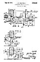
Referring to the drawing briefly, Fig. 1 illustrates a schematic circuit diagram of the piezoelectric oscillator circuit and the resonance indicator of my invention; Fig. 2 illustrates the crystal oscillator portion of the circuit; and Fig. 3 is a circuit diagram used to facilitate explanation of parts of the invention.
The circuit of Fig. 1 makes the use of a high activity high drift type of crystal 10 possible, because the excitation on the crystal is very low at all times for all adjustments of the gap between the crystal and the electrode 11. This electrode 11 is adjustable by means of the knob 13 in a manner such as, for example, illustrated in my prior Patent No. 2,079,540. The first grid 16, cathode 15 and screen grid 17 of the tube 14 constitute the crystal oscillator portion of the circuit together with the crystal 10, the grid leak 2 1, the radio frequency choke 22, condenser 23, source of current supply 24 and resistor 25, as shown in Fig. 2. A by-pass condenser 24a is connected across the source of anode current supply 24. A positive potential is impressed on the screen grid 17 from the source of current supply 24 and consequently this grid electrode acts as an anode. Either one or both the choke coil 22 and the condenser 23 may be variable if desired, particularly if large frequency bands are to be covered. The screen grid 17, however, instead of being grounded to radio frequency, is by-passed to the cathode 15 for radio frequency by means of the condenser 20 and this constitutes the form of feedback employed.
Disregarding for the present the use of feedback in this circuit, reference is made to Fig. 3. In this circuit, the cathode 15 of the tube 14 may be considered at ground radio frequency potential, a radio frequency choke 22 being used to isolate the cathode 15, and the condenser 23 across the radio frequency choke serving as a capacitive reactance in the plate circuit required to cause oscillation. Electric oscillation in the circuit takes place by virtue of the fact that the circuit takes the form of a Colpitts oscillator with the crystal connected between the screen grid 17, which acts as a plate or anode, and the control grid 16, the condenser 23 across the choke 22 giving the proper impedance in the plate circuit for oscillation. This type of circuit produces very little driving action on the crystal, and of course this is desirable since a high-frequency drift coefficient crystal is used. However, it has been found that even though the driving action is adequate in the minimum air-gap position of the electrode 11 this action tapers off and decreases as maximum air-gap is approached. This is detrimental to the performance of the unit, and as a result a slight amount of feedback was added in such a way that the drive on the crystal with the large air-gap was increased without materially increasing the drive when the crystal 10 and electrode 11 are at minimum air-gap position. The feedback then applied in this form has the tendency to smooth out and make the driving action on the crystal constant regardless of whether the air-gap is maximum or minimum. This is accomplished by connecting the grid electrode 17 to the cathode 15 through the condenser 20 thus adding regeneration to the circuit by the amount of impedance voltage drop across the cathode condenser 23; that is, the radio frequency current in returning to ground 22a passes through the cathode condenser 23, shunting the radio frequency choke 22, and the feedback may be varied by varying this condenser and changing the impedance voltage drop across it.
The suppressor grid electrode 18 has a slight positive potential applied to it through the resistors 25a and 26b connected across the source 24, and is grounded to radio frequency through the condenser 26. By doing this, the output from the exciter tube 14 is increased, and at the same time the electrostatic isolation between the circuit of the plate 19 and the crystal oscillator circuit is more complete. The tank circuit 27 connected to the plate 19 is provided with inductance and condenser elements 28 and 29 of such a size that it is possible to tune this tank circuit to both the fundamental frequency and the second harmonic of the crystal oscillator element. This enables a choice of high frequency energy output on several frequency bands, simply by adjusting a variable condenser or by switching in a fixed condenser of appropriate size. The output from the complete unit is taken by coupling a coil 30 and a suitable twisted line or coaxial line 31 to the plate tank inductance 28.
In order to indicate when the tank circuit 27 is tuned to its resonance peak, a resonance indicator 32 is coupled thereto by the inductance 37 connected to the grid 32a and cathode 32c through the condenser 36. This could normally be in the form of a neon tube lightly coupled to the plate tank, but it was found that the neon tube indicator consumed considerable energy. In order not to consume any appreciable amount of the radio frequency energy in the indicating device and at the same time obtain a resonance indicator considerably less expensive than a meter, an electron eye tube 32 is employed to indicate radio frequency resonance without employing a separate rectifier tube, battery or other current source to furnish the bias voltage for the electron eye tube. This was done by simply coupling the grid 32a of the eye tube to the output tank circuit, supplying a bias potential to the grid 32a of the tube by means of a relatively large cathode bias resistor 34, the fixed bias being of such value as to just close the eye when no signal is applied.
The diode load resistor 33 and condenser 36 combination acts to increase the bias potential on the grid 32a when a radio frequency signal is applied to the inductance 37 and by virtue of the effect this bias change has on the plate current, the fluorescent target or electron eye is opened. By properly adjusting the fixed cathode bias resistor 34 the tube can be made to open or close its target on application of a radio frequency signal by working on a different portion of the grid voltage plate current curve. By this means, the tube operates to produce its own bias potential to produce variation in plate current in the tube, and consequently variation in potential on the target electrode 32t with variation in the radio frequency signal.
The crystal oscillator exciter of this invention can be used in amateur and other applications very conveniently. For example if it is desired to operate in the 80 and 40 meter bands, the exciter can be connected to control any existing radio transmitter in these bands. Assuming a crystal frequency of 3600 kilocycles, the output tank circuit 27 can be tuned to 80 meters and by varying the air-gap electrode 11 of the crystal, a frequency variation of 12 kilocycles may be obtained in this band. By simply tuning the output tank circuit 27 to 7200 kilocycles, operation may be obtained in the 40 meter band, a crystal at 3600 kilocycles, giving a continuous frequency variation in the 40 meter band of 24 kilocycles, the output tank of course being tuned to peak resonance by means of the indicating device 32.
In practice I have found that the tube 14 may be a type 1852 or 6AC7 or similar types; resistor 21 is 100,000 ohms; resistors 25, 25a and 25b are 30,000, 20,000 and 100,000 ohms respectively; condensers 20 and 26 are 0.01 microfarad respectively; choke coil 22 is 2.1 milli-henries; and the condenser 23 is variable between 0.00025 and 0.0005 microfarad. The tube 32 is a 6E5 or 6U5 or similar indicator type; resistors 33 and 35 are each one megohm; resistor 34 is 20,000 ohms; and condenser 36 is 0.1 microfarad. It is of course obvious that other values may be used for the foregoing component parts and that this invention is not to be limited to those values since they are given only for the purpose of illustrating one form of practical embodiment of this invention. Furthermore I do not desire to limit this invention to the exact circuit details illustrated except insofar as those details are defined by the claims.
What I claim is as follows:
1. A piezo electric crystal oscillator, comprising: a piezo electric crystal element, a variable air gap holder for said crystal element having an electrode adjustable with respect to one of the principal faces of said crystal element, a vacuum tube having a grid electrode connected to an electrode of said crystal element holder, a cathode for said tube, a source of current supply, an inductance element functioning as a high frequency choke connected between said cathode and a negative terminal of said source of current supply, connections for connecting the other electrode of said holder to said negative terminal, connections for connecting a positive terminal of said source of current supply to another electrode of said tube functioning as an anode, and impedance means connected between said last mentioned tube electrode and said cathode for producing a regenerative effect and slightly driving said piezo-electric crystal throughout the total variation of said variable air gap electrode with respect to the corresponding crystal element face.
2. A piezo electric crystal oscillator comprising: a Piezo electric crystal element, a variable air gap holder for said crystal element having an electrode adjustable with respect to one of the principal faces of said crystal element. a vacuum tube having a grid electrode connected to an electrode of said crystal element holder, a cathode for said tube, a source of current supply, an inductance element functioning as a high frequency choke connected between said cathode and a negative terminal of said source of current supply, connections for connecting the other electrode of said holder to said negative terminal, connections for connecting a positive terminal of said source of current supply to another electrode of said tube functioning as an anode, capacitative impedance means connected between said last mentioned tube electrode and said cathode for producing a regenerative effect and slightly driving said piezo-electric crystal at minimum air gap, and additional means for producing a regenerative effect at maximum air gap of said electrode with respect to the corresponding crystal face, said last means being connected across said high frequency choke.
3. A piezo electric crystal oscillator, comprising: a Piezo electric crystal element, a variable air gap holder for said crystal element having an electrode adjustable with respect to one of the principal faces of said crystal element, a vacuum tube having a grid electrode connected to an electrode of said crystal element holder, a cathode for said tube, a source of current supply, connections for connecting a Positive terminal of said source of current supply to another electrode of said tube functioning as an anode, impedance means connected between said last mentioned tube electrode and said cathode for producing a regenerative effect and slightly driving said piezo-electric crystal, and impedance means connected between said cathode and a negative terminal of said source of current supply to increase the regenerative effect at maximum air gap in the aforesaid holder, and connections for connecting the other electrode of said crystal holder to said negative terminal.
4. A piezo electric crystal oscillator, comprising: a piezo electric crystal element, a variable air gap holder for said crystal element, a vacuum tube having a grid electrode connected to an electrode of said crystal element holder, a cathode for said tube, a source of current supply, an inductance element functioning as a high frequency choke connected between said 'cathode and a negative terminal of said source of current supply, connections for connecting the other electrode of said holder to said negative terminal, connections for connecting a positive terminal of said source of current supply to another electrode of said tube functioning as an anode, impedance means connected between said last mentioned tube electrode and said cathode for producing a regenerative effect and slightly driving said piezo-electric crystal, and a condenser connected across said high frequency choke to increase the regenerative effect at maximum air gap in the aforesaid holder.
5. A piezo electric crystal oscillator adapted for adjustable frequency operation, comprising: a piezo electric crystal having a pair of electrodes one of which is variable to provide a frequency adjusting variable air gap, an electron discharge device having a cathode, a control grid, and another electrode functioning as an anode, said piezo electric crystal having a high frequency drift and being adapted to shift its frequency over relatively wide ranges by virtue thereof when the aforesaid variable air gap is adjusted, a source of anode current supply, connections for connecting said piezo electric crystal through one of its electrodes to said control grid electrode and through the other of its electrodes to the negative terminal of said current supply, a condenser connected between said electrode functioning as an anode and said cathode for producing a slight amount of regeneration when said crystal air gap is substantially at minimum, a high frequency choke connected between said negative terminal of said current supply and said cathode, and a condenser connected across said choke for increasing said regeneration when said air gap is increased for applying a slight driving action to said crystal without exciting said crystal to a point where considerable temperature rise takes place in it.
6. An oscillation generator, comprising: an electron discharge device oscillation generator having a piezo electric crystal oscillator circuit and an output circuit including an anode, said piezo electric crystal oscillator circuit including a cathode, a control grid and a screen grid and means for connecting said piezo electric crystal between said cathode and said control electrode, a source of current supply for said anode and said screen grid, a high frequency choke connected between said cathode and the negative terminal of said source of current supply for maintaining said cathode at a radio frequency potential substantially above zero, and an impedance feedback device connected directly between said screen grid and said cathode, a suppressor grid electrode in said electron discharge device between said anode and said screen anode, means for maintaining said suppressor grid electrode substantially at zero radio frequency potential for electrostatically isolating said anode from said crystal oscillator circuit, and a tuned circuit connected between said last mentioned anode and the positive terminal of said source of current supply.
7. A piezo electric crystal oscillator, comprising: an electron discharge device having a cathode, a control grid, and an anode, a piezo electric crystal having a pair of electrodes, connections for connecting said piezo electric crystal through one of its electrodes to said control grid electrode, a source of current supply, an output circuit connected between said anode and the positive terminal of said source of current supply, means connected between said cathode and said output circuit for producing a slight amount of regeneration between said output circuit and the circuit of said piezo electric crystal for applying a slight driving action to said crystal, and a high frequency choke having one terminal connected to said cathode, the other terminal of said high frequency choke being connected to the other electrode of said piezo electric crystal and to the negative terminal of said source of current supply.
JOHN M. WOLFSKILL.
>> End of Patent <<