| Union (Railway) Station Building, 1935-1966 |
| Union (Railway) Station Building, 1935-1966 |
In 1933, the Bliley Electric Company had outgrown the space it used in the Masonic Temple Building at the corner of 8th and Peach Streets. The next stop was the new Union Station building, the primary railway station in Erie. It is located at the intersection of 14th and Peach Streets. The new building's primary tenant was the New York Central railway line, but there was space for the Railway Express (freight) offices, a small lunch bar for travelers, and several floors of commercial office space. The company rented space on the second floor. In the years that followed, Bliley Electric eventually grew to take over the entire second and third floors of the building covering an area of approximatly 32,000 square feet. The Union Station can be seen in the drawing below.
The Union Station was replaced by a new 40,000 square foot plant, constructed by Bliley's, in the Southwestern edge of the city of Erie on Grandview Boulevard in 1966.
 Below is a collection of photos
I found in my archives of the company. The date and purpose of
the photographs is uncertain, but they are no doubt from the Union
Station and many carry a note of "1936?" on the back.
Virtually the same setups were rephotographed for the first large-scale
and comprehensive product line catalog, G-9, in 1936. Were these rejected prototypes
for an early draft of that catalog? From analysis of the equipment,
the photos are no earlier than the April of 1935 as John Wolfskill
appears in one of them. The date is also based on release dates
for some of the radio equipment seen one the photo. Several of
these photos were heavily touched up to paint out background debris
and the company logo of a previous employer on one man's shirt.
There is no doubt that this set of photos was to be used as photographic
masters and not to be used directly in the form that I found them.
Below is a collection of photos
I found in my archives of the company. The date and purpose of
the photographs is uncertain, but they are no doubt from the Union
Station and many carry a note of "1936?" on the back.
Virtually the same setups were rephotographed for the first large-scale
and comprehensive product line catalog, G-9, in 1936. Were these rejected prototypes
for an early draft of that catalog? From analysis of the equipment,
the photos are no earlier than the April of 1935 as John Wolfskill
appears in one of them. The date is also based on release dates
for some of the radio equipment seen one the photo. Several of
these photos were heavily touched up to paint out background debris
and the company logo of a previous employer on one man's shirt.
There is no doubt that this set of photos was to be used as photographic
masters and not to be used directly in the form that I found them.
Some of the photos had captions written on them, and that is obvious. I have made educated guesses as to the activities in the others. In either case, these are a rare glimpse into the inner workings of this company in its very early days.
Charles A. Bliley
August 2001
 Low-Rez 72 dpi (28K) High-Rez 144 dpi (81K) |
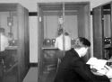
BASIC RESEARCH All good products begin with a good idea that is transformed into a reproducible product. Here is John Wolfskill, a recently hired electrical engineer (April 1935). John will go on to serve as the chief engineer and be credited with securing 29 patents in his name for Bliley Electric.This is the virtually the same photo of him as appears on Page 2 of the 1936 product line catalog. |
 Low-Rez 72 dpi (32K) High-Rez 144 dpi (106K) |
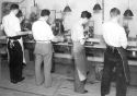
CALIBRATION Screen rooms isolate one test and evaluation station from another. Here technicians check the parameters of finished products and record the final operating frequency. |
|
 Low-Rez 72 dpi (15K) |
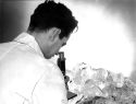
INCOMING INSPECTION The finished product is no better than the raw products. This was true in 1935 and is still true today. Here is a somewhat contrived photo of a man inspecting crystals with a microscope. The raw quartz is simply too large to be viewed with this instrument. However, the microscope may have been used to inspect thin blanks cut from the quartz. |
 Low-Rez 72 dpi (20K) High-Rez 144 dpi (56K) |
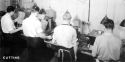
CUTTING/SLICING After examination for the crystals axis, the raw quartz is cut into think wafers using diamond saws. This process would alter be referred to as "slicing"--a term used today. |
|
 Low-Rez 72 dpi (38K) High-Rez 144 dpi (66K) |
CUTTING/SLICING-- This is a shot of a second slicing work area. |
 Low-Rez 72 dpi (49K) High-Rez 144 dpi (82K) |
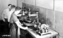
LAPPING After the crystal blanks are cut to the approximate size, the rough-cut blanks are lapped (ground) to move blank a step closer to the final frequency. Usually, dozen of blanks are lapped at once to improve efficiency. |
|
 Low-Rez 72 dpi (29K) High-Rez 144 dpi (86K) |
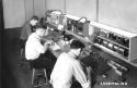
HOLDER AND CRYSTAL UNIT ASSEMBLY Here is a group of men building the holders and assembling the crystals after the blanks have been calibrated. The next step--not shown here--is the final calibration and testing with the unit in the holder. In the foreground is John Pinar, who served Bliley's for 39 years--most of that time as the supervisor/foreman of the Calibration Department. |
 Low-Rez 72 dpi (39K) High-Rez 144 dpi (71K) |
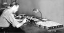
FINAL ASSEMBLY AND PACKAGING Here sits the person who is responsible for putting the finished crystals, their operating instruction sheets, and packing material into boxes. Depending on the model, the operating frequency and a serial number were written on the crystal unit and its box. This photo shows 80-meter amateur radio units being assembled. The man in the photo is Robert Johnson, who served in many capacities, starting with draftsman and finally as the company's "industrial relations manager"--what we now call human resources. Bob retired from Blileys with 37 years of service. |
|
 Low-Rez 72 dpi (37K) High-Rez 144 dpi (122K) |
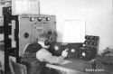
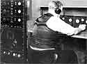
FREQUENCY MEASUREMENT SERVICES The company also used this fine and expensive setup to sell frequency measuring and certification services to commercial stations such as those in the broadcast industry. This could be done on a one-time basis, or as a subscription. In order for the crystals to be calibrated, they needed an accurate frequency standard as a point of reference. Here is a work station that contains the General Radio master oscillator that serves as the company's primary standard. This standard is verified every morning by comparing it to a signal broadcast by the United States Navy. |
 Low-Rez 72 dpi (40K) High-Rez 144 dpi (128K) |
CALIBRATION DEPARTMENT'S REFERENCE OSCILLATOR This is the second master oscillator synchronized to the master oscillator seen in the righthand photo. From this workstation station each of the final calibration technicians would ask for a reference frequency to be patched to them in the screen rooms. With the use of the oscillator panels and homemade mixers, each calibration station would have a precise frequency to use in the work. The man at the station is Bob Schlaudecker who spent much of his 30+ years at Bliley's in charge of the HF crystal lab. |
|